The question comes up constantly in manufacturing quality labs: should we be using our CMM or our 3D scanner for this inspection task? The honest answer is that it depends, but it depends on specific, knowable factors, not on habit or what was already in the lab when you got there.
CMMs have been the gold standard for dimensional metrology for decades, and for good reason. But 3D scanning technology has matured to the point where it is the more practical choice for a significant portion of real-world inspection tasks. The key is knowing which portion.
This guide cuts through the tool loyalty and gives you a practical framework for choosing the right instrument for each inspection task.
How Each Tool Actually Works
Coordinate Measuring Machines (CMM)
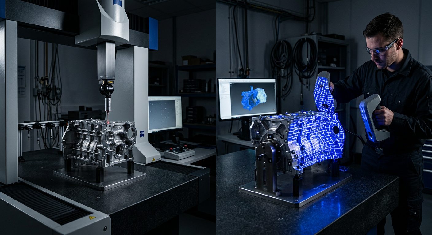
A CMM measures individual points on a part's surface using a tactile probe, a precision stylus that physically contacts the part. It reports the X, Y, Z coordinates of each contact point with very high accuracy, typically in the range of a few microns or better for high-end machines in controlled environments.
The CMM builds its measurement picture one point at a time. To measure a bore diameter, it touches the bore wall at multiple points and fits a circle. To measure a flatness callout, it probes the surface at multiple locations. The accuracy of the measurement depends partly on the number of points collected and how well they represent the feature's actual geometry.
3D Scanning
A 3D scanner captures the surface geometry of a part as a dense point cloud, potentially hundreds of thousands to millions of measurement points in a single scan pass. Rather than probing discrete features, the scanner captures the entire visible surface simultaneously.
For inspection purposes, this point cloud is then aligned to the nominal CAD model and analysed in software like Geomagic Control X, which evaluates every measured point against its designed position and generates colour-coded deviation maps, GD&T callout results, and inspection reports.
Where the CMM Still Wins
Sub-micron accuracy requirements
High-end CMMs in temperature-controlled metrology labs achieve measurement uncertainties in the range of 1-3 microns. Industrial 3D scanners, even the best portable metrology-grade systems, typically achieve accuracy in the range of 15-50 microns. For parts with extremely tight tolerances, such as precision bearing seats, high-performance fuel system components, or gauge blocks, CMM accuracy is still unmatched.
Simple prismatic geometry with tight GD&T callouts
When a part is predominantly prismatic, composed of planes, cylinders, and bores, and the inspection requirement centres on a small number of critical GD&T callouts, a CMM is often faster and more defensible than a scanner. The CMM's point-by-point approach is well-suited to evaluating discrete features against defined tolerances, and the measurement routine can be programmed to repeat exactly for production sampling.
Established regulatory or quality system requirements
In some aerospace and defence quality environments, the CMM-based inspection process is written into the quality plan and may be required by customer or regulatory specification. In these cases, the question of CMM vs scanning is not a free choice, the CMM is specified. This is worth checking before investing in a scanning-based inspection workflow for a customer-audited quality system.
Long-run production sampling
CMM programs, once qualified, run with excellent repeatability and require minimal operator intervention. For high-volume production environments where the same part is inspected thousands of times, a programmed CMM routine is hard to beat for throughput and consistency.
Where 3D Scanning Wins
Complex freeform and organic geometry
This is the clearest case for scanning. A CMM can only inspect a freeform surface by probing many individual points, and even with dense point sampling, it will miss geometric deviation between the probed points. A 3D scanner captures the entire surface continuously. For castings, forgings, turbine blades, automotive body panels, plastic moulded parts, and any geometry with compound curves, scanning provides a genuinely better picture of what is happening across the surface.
Full-surface deviation analysis
A CMM tells you whether specific features pass or fail their callouts. A 3D scanner, combined with Geomagic Control X, shows you the deviation pattern across the entire part surface, colour-coded, quantified, and mapped against the nominal. This is invaluable for diagnosing process problems: a CMM result that says a surface is out of tolerance tells you it failed. A scan deviation map tells you exactly where, by how much, and in what pattern, which tells you why, and what to adjust in the process.
Speed for first article and incoming inspection
For first article inspection on a complex part, setting up a CMM program from scratch can take hours. A scanning workflow, scan, align, run inspection routine in Control X, generate report, can produce a comprehensive first article result in a fraction of the time. For incoming inspection of varied parts from suppliers, the flexibility of scanning is a significant throughput advantage.
In-field and non-laboratory inspection
CMMs require a controlled environment, level, vibration-isolated, temperature-stable. A portable 3D scanner can inspect a part on the shop floor, at a supplier's facility, or in the field. For large assemblies, weldments, or installed components that cannot practically be moved to a metrology lab, portable scanning is the only practical option.
Large parts
CMM working volumes are fixed. Inspecting a large part often requires repositioning with associated alignment uncertainty. Photogrammetry-referenced 3D scanning can inspect large assemblies with metre-level dimensions while maintaining sub-millimetre accuracy across the full volume, which is impractical for most fixed CMM installations.
Side-by-Side Comparison
| Factor | CMM | 3D Scanning |
|---|---|---|
| Typical accuracy | 1–5 microns (lab-grade machines) | 15–50 microns (metrology-grade portable) |
| Data density | Sparse, discrete points on features | Dense, full surface coverage |
| Freeform surfaces | Limited, point sampling only | Excellent, captures full geometry |
| GD&T callout inspection | Excellent, purpose-built | Good, fully supported in Control X |
| Setup time (new part) | Hours to days for complex programs | Minutes to hours |
| Deviation visualization | Limited, point results only | Excellent, colour maps of full surface |
| Portability | Fixed installation | Highly portable (handheld scanners) |
| Large parts | Limited by machine volume | Excellent with photogrammetry |
| Environment requirements | Controlled lab (temp, vibration) | Flexible, shop floor capable |
| Reporting | Feature-by-feature pass/fail | Full-surface deviation + GD&T in Control X |
How to Choose for Your Next Inspection Task
Use the CMM when...
- Tolerance is tighter than 20 microns
- Part is prismatic with discrete feature callouts
- You need a repeatable production sampling program
- Customer or quality system specifies CMM
- Working in a temperature-controlled lab environment
- Part volume fits within CMM working range
Use 3D scanning when...
- Part has complex freeform or organic geometry
- You need full-surface deviation analysis
- Speed matters, first article or incoming inspection
- Part is large or cannot be moved to the lab
- You need to diagnose a process problem visually
- Tolerances are 50 microns or looser
The Hybrid Approach
The most sophisticated quality labs do not treat this as an either/or. They use scanning for initial, comprehensive surface analysis and CMM for verification of specific critical features where the tight tolerance requirement demands CMM-level accuracy.
"Scan the part to understand it. Use the CMM to certify the critical features. That combination gives you the full picture and the defensible measurement data, without running the CMM program on every feature when only a few actually need that level of scrutiny."
A practical example from automotive: scan a stamped body panel to evaluate the full surface against the nominal, this catches springback, warpage, and tool wear patterns that a CMM-only approach would miss. Then take the CMM to the three or four feature callouts (datum holes, critical flange dimensions) that carry the tightest tolerances. Two tools, two different jobs, better total information.
What This Means for Geomagic Control X
Control X is built for both modalities. It accepts point cloud and mesh data from 3D scanners, and it can import CMM measurement data for analysis and reporting within the same platform. Teams running hybrid workflows can generate comprehensive inspection reports that combine scanning-derived surface analysis with CMM point measurements, all within a single report structure.
If you are building or evaluating a dimensional inspection workflow that uses both CMM and 3D scanning data, the workflow design and data management between the two tools is where most teams run into problems. That integration is exactly the kind of engagement we specialise in.
If you are working through this decision for your own quality program, we have been helping teams design inspection workflows for over 17 years. We are familiar with most part types, most scanner platforms, and most of the integration challenges that come up when combining scanning and CMM data. If a conversation would be useful, we are easy to reach.
The question is not which tool is better. The question is which tool is right for the tolerance, geometry, and reporting requirement in front of you right now. Once you build that decision logic into your quality workflow, the right answer becomes automatic, and both tools get used where they are actually effective.